Amada Promecam
A practical guide to the Amada Promecam tooling interface and five key measurable values—clamping type, tonnage, height, hardness, and tang tolerance—that determine whether a tool set is compatible with your customer's machine.
When a vendor quotes press brake tooling, the first question is always: Will this set fit my customer's machine? The answer rarely hinges on brand names. It depends on five measurable values that can be verified with calipers, a nameplate, and a drawing. Amada Promecam is the most widely replicated tooling interface globally—which also explains why mislabeling is so common. Knowing what the standard defines and what it leaves to the machine builder determines whether you get a repeat order or a returned pallet.
We manufacture press brake tools hardened to HRC 8-62 in 42CrMo,, and ship standard dies within three to five days. The specifications below reflect our production floor standards.
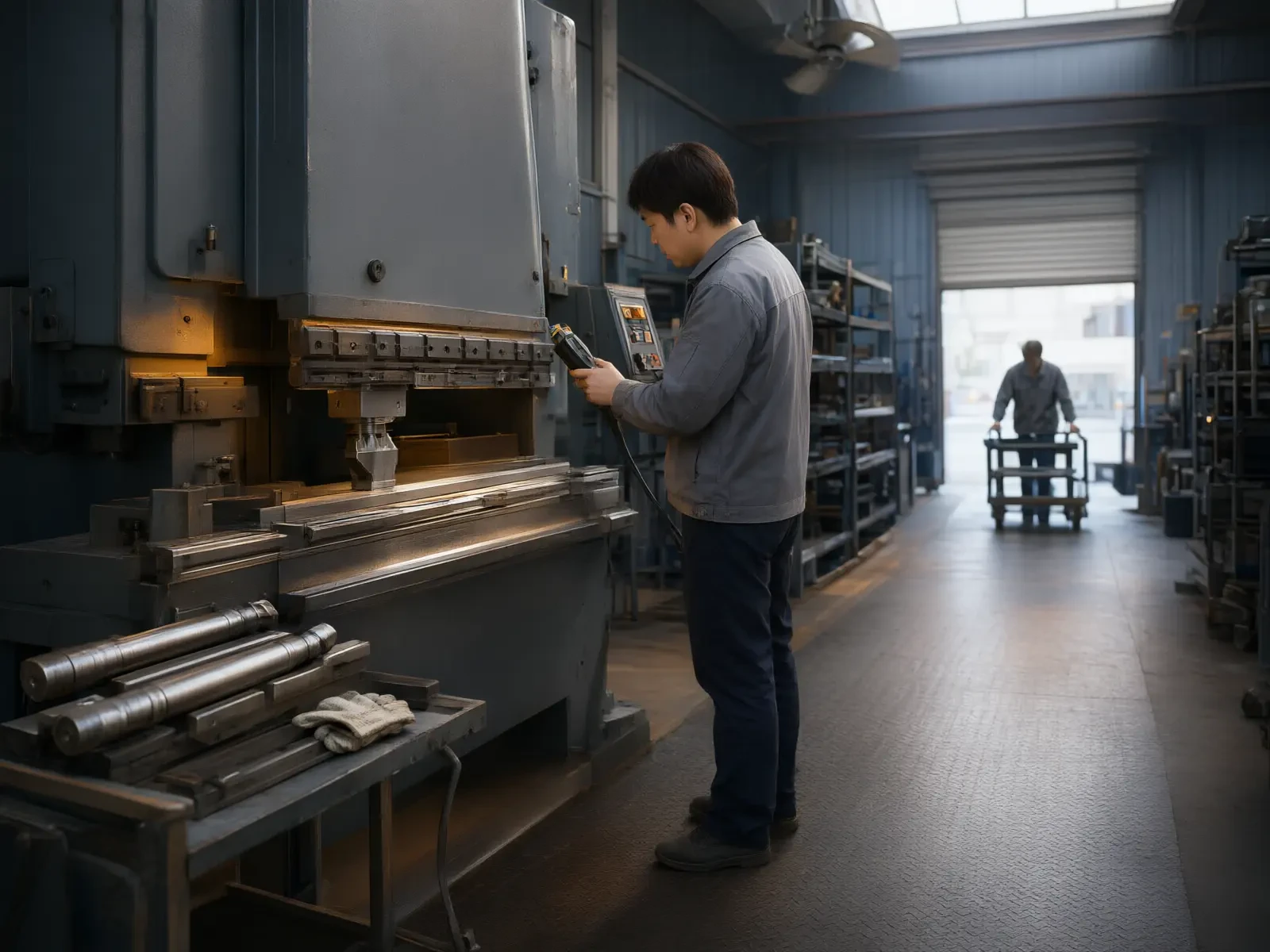
The Promecam interface only fixes the clamping, not the entire tool.
The Promecam system secures a punch by seating its narrow tang into a clamp block on the upper beam, while the die rests in a base rail on the lower bed. Once this interface is matched, working geometry may still vary between catalogues.
This is where traders lose time. Two punches both marketed as Amada Promecam can have different overall heights, tip radii, and section splits. The interface is a compatibility promise; the rest is an engineering choice. Confirm tang dimensions against the clamp block drawing before quoting, and treat the label as a starting point—not proof.
The Amada original Japanese clamping system uses a separate interface. Tools designed for one system will not fit the other without adapters. When a customer specifies a machine model, request photos of both the clamp and the die rail. One image clarifies more than three emails.
Tonnage is the first to fail.
Tooling capacity is rated in kN/m—the bending force it can withstand per meter of working length. The machine also has a rating, typically expressed as total tonnage distributed across the beam. Exceeding either limit will cause cracking; failure manifests at the punch tip or die shoulder long before the machine stalls.
For air bending mild steel, the force per meter follows this working relationship:
P (kN/m) ≈ 650 × t² / V
where t is material thickness in millimeters and V is the die opening in millimeters. A 3 mm mild steel part bent over a 24 mm V-die requires approximately 244 kN/m. Stainless steel and high-tensile grades increase this value, and a 400 mm bend on a punch rated for 500 kN/m leaves margin that a 900 mm bend does not.
The practical rule for traders is to quote the tonnage alongside the tool, not after the customer asks. This shortens the approval cycle and eliminates the most common cause of field failure. Die opening selection follows the same logic: use a V-groove approximately eight times the material thickness for mild steel; go narrower for thin gauges and wider for thick plates where punch load becomes the limiting factor.
Height, open height, and stroke determine part fit.
A tool set may be dimensionally correct yet still unable to form the part. Three vertical dimensions determine this: punch height, die height, and the machine's open height between the bed and ram in the up position. Adding stroke and shut height leaves only a fixed amount of space for the workpiece—a hard constraint.
Deep boxes, return flanges, and parts with tall side walls require clearance beyond what the standard setup provides. In these cases, sectional punches and horn dies are used. A segmented punch in standard lengths allows the operator to remove the section above the flange and bend around it. Die height is critical for the same reason: a shorter die lowers the working plane but also reduces how far the part can drop below the bend line.
Request the part drawing before recommending sections. The drawing specifies flange depth, which determines whether a standard punch or an extended version is required.
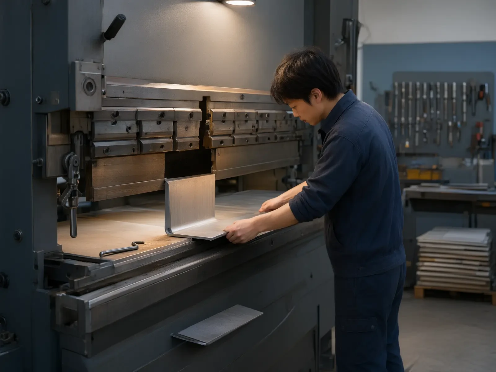
Separate suppliers for hardness and tang tolerance
42CrMo at HRC8-62 is the baseline for standard punches and dies in this class. The range matters less than its distribution. A punch reading 60 HRC at the tip and 52 HRC at the tang will wear unevenly, with clamping force concentrated at the tang.
Our production maintains a ±0.01 mm tolerance on critical mating surfaces, verified via ISO9001 inspection at the end of each batch. For traders evaluating a new supplier, three key checks are essential: hardness readings at three points along the working edge, tang width measurements on both ends, and a straightness check across the full length. Any tool with variation exceeding 0.05 mm over its length will be rejected.
Five values to collect before providing a quote
Every tooling quote can be finalized with this concise list: machine model and clamping type; working length and tonnage rating (kN/m); material grade and thickness; die opening or target inner radius; part drawing with flange depth.
With these five, suppliers can match standard punches and press brake die sets from the catalog or mark the job as custom. Our standard range ships in 3–5 days; custom profiles take 15–20 days. The lead time difference is almost always determined at the quoting stage, not during production.
Traders who secure these details upfront spend less time revising and more time on the next inquiry. Contact us with a machine model and part drawing, and we will return the matching tool set along with its tonnage rating and delivery date.
Need help matching tools to a machine?
Send us the machine model and part drawing. Our team will confirm the compatible tool set and tonnage rating.
Get a Quote